Замена главной пары в специализированном сервисе
Если замена предполагается в специализированном сервисе, то при обращении желательно уточнить несколько моментов:
- в автосервисе есть механик имеющий опыт в установке и регулировке главных пар, соответсвенно у него должен быть весь необходимый инструмент(как минимум пресс, индикатор биения, динамометрический ключ) и необходимые расходники - регулировочные шайбы, краска для редукторов, клей для фиксации резьбы и т.п.
- в автосервисе есть необходимые расходники для замены, либо они их смогут самостоятельно приобрести при необходимости - сальник, втулка, гайка, подшипники, трансмиссионное масло.
- попросить сделать фото пятна контакта после сборки. В идеале требовать предоставить протокол установки включая толщину используемой шайбы, биение привалочной поверхности, разброс теплового зазора по зубам, преднатяг подшипников, а также предоставить видео биения привалочной поверхности дифференциала со снятой парой и видео промера теплового зазора по нескольким зубам после финальной сборки. Гарантия на главные пары может быть рассмотрена только при наличии этой информации, т.е. подтверждения, что работа была выполнена правильно.
- уточнить какая гарантия на выполненные работы и спросить рекомендации по обкатке после завершения работы.
Предупреждение: Хорошие специалисты обычно загружены работой и работают по записи.
Замена главной пары невозможна за "полчаса", так как процесс регулировки включает в себя:
- полный разбор и мойку редуктора
- дефектовку всех комплектующих, включая измерение биения поверхностей
- многократное снятие и установку подшипников для выставления правильного пятна контакта путем подбора шайбы необходимой толщины
- определение и корректировку преднатяга подшипников
- выставление теплового зазора с помощью индикатора
- финальная сборка с использованием клея для фиксации резьбы, установкой новых сальника, втулки и гайки
Сминаемая втулка, гайка и сальник хвостовика - одноразовые детали, лучше если вы их сразу принесете вместе с главной парой для замены. (Втулки бывают несминаемые "многоразовые" на некоторых редукторах)
Рекомендуем обратиться к одному из наших проверенных партнеров - специалистов по установке главных пар.
Замена главной пары своими силами или у специалиста под вашим контролем
1. Прежде чем приступить к снятию и разбору редуктора для замены главной пары обязательно:
- проверьте что имеющаяся у вас главная пара подойдет именно на этот редуктор;
- ведущая и ведомая шестерня соответсвует маркировке и цифры химическим карандашом на них совпадают;
- проверьте что отсутсвуют видимые дефекты - отколотые зубы, шлицы и резьба нормальные;
- проверьте что количество зубов на ведущей и ведомой шестерне соответсвует маркировке на паре и необходимому передаточному числу (Необходимо поделить кол-во зубов на "круглой" шестерне на кол-во зубов на "морковке". Например 39 зубов на "круглой" и 8 на "морковке" соответсвуют передаточному числу 4.88 = 39/8);
- сохраните упаковку на случай обмена данной пары у продавца если она вруг не подойдет по какой-то причине.
- приобретите заранее одноразовые детали для установки - сминаемую втулку, сальник и гайку. А также уточните сможете ли вы купить подшипники в ближайшем магазине в случае если они понадобятся.
2.
4. Установленная новая главная пара требует обкатки в обязательно порядке, более того соблюдение правил обкатки является неотемлемой частью гарантии.
Подробнее можно ознакомиться в этой статье, а также в руководстве от Nitro-gear.
Как обкатывать новую пару после установки
После установки все новые наборы нуждаются в обкатке пар для предотвращения поломки от перегревания. Любая перегрузка или перегревание портит масло, которое, в свою очередь, приводит к поломке пары. Это легко определяется при просмотре. Гарантия не действует, если поломка произошла по вышеуказанным причинам.
Далее....
-Избегайте сильного ускорения во время обкатки;
-В самом начале нужно аккуратно проехать на машине 15-20 миль (24-32 км), остановиться и дать охладиться паре; после этого продолжить поездку.
-Избегайте быстрого ускорения первые 100 миль (160 км).
-Буксировка разрешена только после того как Вы проехали более 500 миль (800 км), иначе Вы лишаетесь гарантии.
-Для первой буксировки нужно проехать на загруженной машине короткое расстояние 15 миль (24 км) и остановится на 20 мин для охлаждения пары. Повторить этот процесс еще 2 раза для полной обкатки пар (всего 45 миль обкатки (72 км)).
-Необходимо поменять масло после первых 500 миль (800 км). В результате этого Вы убираете частички металла и фосфорного покрытия, которые попадают в масло в результате обкатки пары.
Эти инструкции могут показаться ненужными, но мы можем Вас уверить, что мы видели много случаев поломанных пар, вызванных в результате пренебрежения правилами инструкции.
ПЕРЕЗАГРУЖЕНАЯ МАШИНА ИЛИ ПЕРЕГРЕТОЕ МАСЛО ПРИВИДЕТ К ПОЛОМКЕ ВАШЕЙ ПАРЫ !!!
On this page: Tool List | Disassembly | Inspection | Assembly | Tooth Nomenclature | Patterns | Break In
Differential Installation Instructions
Please read completely before beginning.
You can expect many years and many miles of dependable use from your differential if it is set up properly and if you use only top quality parts. You already have quality parts if you bought them from West Coast Differentials. By following these differential installation instructions carefully, you will achieve proper set up. We have successfully set up thousands of differentials without using a pinion depth setting tool. We sincerely hope that these instructions are helpful.
Tool List
When working on your differential you will need a wide variety of tools. Using the correct tools saves time and helps prevent parts from being damaged. Here is a list of some of the tools that you may need:
- Dial indicator
- Gear marking compound and a clean brush
- Calipers or a micrometer
- Bearing pullers
- Bearing press
- Three foot long breaker bar or strong impact gun
- Pinion nut socket
- Ring gear bolt socket
- Carrier cap bolt socket
- Six point cross pin bolt wrench
|
- Brake line wrench
- Pry bars for removing the carrier case
- 24 oz ball pein hammer
- 48 oz sledge hammer
- 48 oz plastic dead blow hammer
- Assorted brass punches
- Punch for marking carrier caps
- Oil drain pan
- Foot pounds torque wrench
- Inch pounds torque wrench
|
Back to Top
Disassembly
Make sure that you have all the parts and tools you will need. The extent of disassembly depends on the job being done and the inspection findings. Lift the vehicle using an appropriate lift or a jack and safe jack stands. Always make certain that the vehicle is safely supported before working underneath. Unbolt the driveshaft from the yoke. Remove the differential cover or unbolt the third member. Let the oil drain into a suitable container. Please recycle your waste oil. Remove c-clip axles by removing the differential cross pin bolt and cross pin shaft, pushing the axles in and pulling the c-clips. Full float axles are unbolted at the hubs. Punch both carrier caps with identification marks so that you will be able to re-install them on the same side and in the same direction. Most carriers can be pried out of the housing with a pry bar. Further disassembly depends on the job being done. If you’re changing the ring and pinion or the pinion bearings, remove the pinion nut with an air gun while holding the yoke, or use a long breaker bar and brace the yoke (bolt it to a long board) so that it can’t move. Knock the pinion gear out to the rear with a brass punch, taking care not to damage the threads. Keep track of the location and thickness of all of the original shims. Pinion bearings must be pressed off. Carrier bearings can be pulled using a bearing puller. Internal parts (inside the carrier) can be removed as necessary.
Back to Top
Inspection
- Inspect all bearings and races for pitting or uneven wear. The inner carrier bearing races should not spin on the carrier journals. The carrier races should have a snug fit in the housing.
- Inspect the carrier race bores for grooves from spinning races. The side gear bores inside the carrier should not have any abnormal wear. All gear teeth (including the spider gears) should be smooth but not excessively shiny.
- Inspect all gear teeth for pitting, chips, breaks, and for signs of uneven wear and overheating.
- Inspect positraction clutches for scoring and wear.
- Inspect the axles for pitted, grooved, or dull and rough bearing surfaces. Check for worn axle splines. All questionable parts should be replaced.
Back to Top
Assembly
Differential Adjustments
The four essential differential adjustments are pinion depth, pinion bearing preload, backlash and carrier bearing preload. The tables at the back can be used to write down shim combinations and results.
Preparing Parts
Clean all new and used parts with clean solvent. Dry the parts. De-burr the back of the ring gear and carrier mounting surface with a file or wet stone. Wash out the housing with solvent and check all of the oil passages for metal particles or dirt that can lead to early wear. Many housings have oil passages to the pinion and grooves just outside of the carrier bearings. Push rags through the axle tubes, using solvent or brake cleaner until they are clean. Polish all seal surfaces with light emery cloth or fine sandpaper and then wipe them with a clean rag and clean oil or solvent to remove metal particles. Use a moderate coat of gear oil (not grease!) on all bearings and grease (not oil) on all seals and seal surfaces just prior to installation.
Initial Assembly
Pinion depth shims either go under the rear pinion race or on the pinion shaft under the rear pinion bearing. The diameter of your shims will determine where they go. Try using the original shim depth for your first attempt. The rear pinion bearing must be pressed on the pinion shaft and the pinion races must be tapped into the housing with a large punch so that they seat evenly. Install the front bearing and carefully tap the pinion seal in place with an old race. Ford 8? and 9?, and GM 10.5? and 12.25? use a pilot bearing which must be tapped in, with a retainer for the Fords. Mount the ring gear to the carrier with a drop of red Loctite on each bolt. Carrier bearings are pressed on the carrier and secured with green Loctite. Note that in Dana Spicer differentials the carrier shims go between the carrier and carrier bearings. Again, try using the original shim configuration.
Install Pinion Gear and Set Pinion Bearing Preload
Pinion bearing preload is measured in inch-pounds, and is a measure of the rolling resistance of the pinion bearings after proper torque has been applied to the pinion nut. Set the preload carefully (see “Set Up Specifications”) so that the bearings will have a long life. Use oil on the pinion nut washer surface during all assemblies and red Loctite on the pinion nut threads during the final assembly.
Crush Sleeve Design: If you are unsure about getting the correct pinion depth, it may be easier to install the pinion without a crush sleeve until the correct pinion depth has been established. Always use a new crush sleeve for final assembly. Slide the crush sleeve on the pinion shaft (unless you are using the trial and error method) and install the pinion through the rear of the housing. The yoke usually must be tapped on while applying pressure on the pinion gear head to hold it in place. Use an impact wrench or huge breaker bar to apply the torque necessary to crush the sleeve. Proceed very slowly so that you don’t overload the bearings. The pinion preload will be zero until the bearings contact the races but will then increase very quickly. Use an inch-pound torque wrench to check the preload. If the pinion bearing preload exceeds the specified allowable range, install another new crush sleeve and start over.
Preload Shim Design: Clean the shims completely so that there are no particles that may cause a false preload reading or cause the shim stack to change thickness over time as the vehicle is driven. Slide the shim pack over the pinion shaft to the shelf. Use the original shims on the first assembly or add 0.003? to the original preload shims to make up for the bearings settling into the housing. Tighten the pinion nut to approximately 250 foot pounds. Go slowly so as not to damage the bearing if the preload shim stack is not thick enough. Use an inch-pound torque wrench to check the preload. If the preload is too loose then remove shims so that the bearings will be tighter against the races and increase the preload. If the preload is too tight then remove the pinion gear and add shims so that the bearings will not be as tight against the races.
All Designs: After reaching the correct preload, moderately tap both ends of the pinion to seat the bearings, races and yoke. Be careful not to hit the pinion so hard that it damages the bearings. After “seating” the pinion, check the pinion bearing preload again.
Install Carrier and Adjust Carrier Preload and Backlash
Carrier bearing preload is not specifically measured, but a good tight fit is important in all differential designs. Inadequate carrier bearing preload allows the carrier to move when under load and this can cause the backlash to open up. Check the backlash by mounting a dial indicator to the housing with the plunger set perpendicular to the ring gear teeth. Hold the pinion yoke and rotate the ring gear back and forth. See the specifications section. The backlash will generally change about 0.007? for each 0.010? that the carrier is moved. To decrease the backlash, move the carrier closer to the pinion centerline. To increase the backlash, move the carrier away from the pinion centerline.
Screw Adjuster Design: Oil the adjuster threads on both the housing and on the adjusters themselves. While holding the races on the bearings, place the carrier in the housing. Install the carrier caps according to the marks made during disassembly so that the threads are seated evenly on the adjusters. Third member differential designs require a 10 to 12 inch spanner wrench to tighten the adjusters. Chrysler differential designs require an extension bar and special spanner to access the adjusters through the axle tubes. Tighten both the left and right adjusters evenly by hand until they are fairly tight. If the backlash is too wide, tighten the left adjuster until the backlash is correct. If the backlash is too tight, tighten the right adjuster until the backlash is correct. If necessary, open one adjuster and tighten the other. Both adjusters must be fully hand tightened when acceptable backlash is obtained. The final adjustment should tighten the left adjuster since the ring gear is forced away from the pinion gear while under load.
Shim Design: Some differentials use shims between the carrier bearing races and the housing and some use shims between the carrier bearing and the carrier case. Carrier bearing preload is established by the tightness of the shims. The carrier should be shimmed tight enough that it must be tapped in with a plastic dead blow hammer. While holding the races on the bearings (and outside shims on the races) start the carrier into the housing and tap it in with the hammer. Install the carrier caps according to the marks made during disassembly. Check the backlash. If the backlash is too wide, move or add shims to the left side. If the backlash is too tight, move or add shims to the right side. (If the carrier is snug, move and replace the same thickness; if the carrier is too tight or too loose, remove or add shims accordingly.)
Back to Top
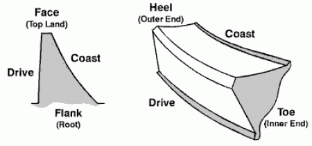
Tooth Nomenclature
| (Terms for describing specific areas of the gear teeth) |
 |
Back to Top
Checking the Pattern
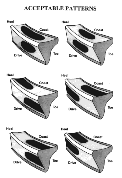
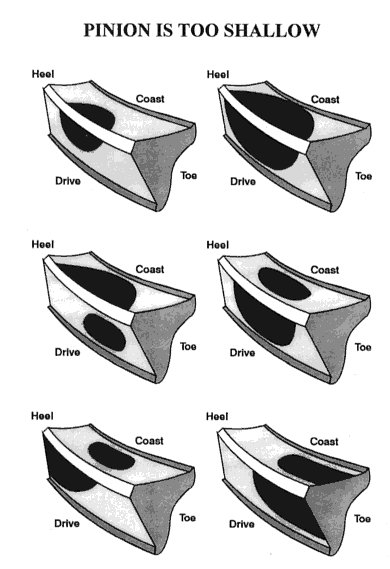
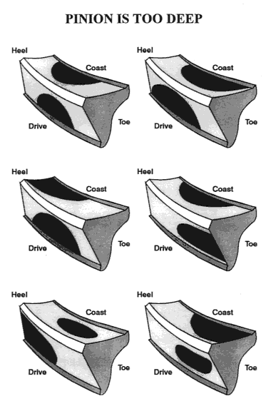
Check the pattern for proper pinion depth only after setting the backlash. Brush three or four of the ring gear teeth with a moderate coat of gear marking compound in two different places on the ring gear. Rotate the ring gear past the pinion gear three or four times and then back so the pattern can be seen.
Pinion depth is indicated by the position of the pattern between the face and flank of the ring gear teeth. Backlash must be kept within specifications, and will therefore only slightly affect the pattern between the heel and toe of the ring gear teeth. Housing alignment and pinion bearing bore alignment can also affect the pattern from heel to toe and can not be corrected without machine work. In some cases an ideal heel to toe pattern can not be achieved. If the backlash is within specifications, you may disregard the heel to toe pattern. A contact pattern that is centered from face to flank always indicates correct pinion depth even if a pattern that is centered from heel to toe can not be obtained.
If the contact pattern is towards the face of the ring gear teeth then the pinion is too far away from the ring gear. Adjust the pinion shims to move the pinion gear towards the ring gear centerline (add shims; subtract shims for pinion support designs). If the contact pattern is towards the flank of the ring gear teeth then the pinion is too close to the ring gear. Adjust the pinion shims to move the pinion gear away from the ring gear centerline (subtract shims; add shims for pinion support designs).
 |
 |
 |
Acceptable Contact Pattern
(click image to enlarge) |
Pinion is too shallow
(click image to enlarge) |
Pinion is too deep
(click image to enlarge) |
When changing the pinion depth, make large changes (0.005? to 0.015?) until the pattern is close. By making adjustments that move the pinion too far, you can determine that the correct pattern is somewhere between the two extremes. Then make smaller changes (0.002? to 0.004?) until the pattern is centered between the face and the flank of the ring gear teeth.
When setting up a used ring & pinion, pay more attention to the pattern on the coast side of the ring gear teeth and pay less attention to the drive side. Low mileage gears should be patterned as if new.
Back to Top
Gear Oil, Additive and Break-In
Use a gasket or 100% silicone to seal the cover or third member to the housing. Use only high quality name brand gear oil and fill the differential until the oil spills out the plug hole. Positraction carriers require anti-friction additive. All new gear sets require a break-in period to prevent damage from overheating. After driving the first 15 or 20 miles you must let the differential cool for 30-40 minutes before proceeding. Drive 500 easy miles before towing. Tow for very short distances (less than 15 miles) and let the differential cool before continuing during the first 45 towing miles. Change the gear oil after the first 500 miles. This will remove any metal particles or phosphorus coating that has come from the new gear set.
Any overloading or overheating can cause the gear oil to breakdown
and the Ring & Pinion can fail
Back to Top
